New UPS Options with Compact Designs, Batteries, Cooling Requirements
Part 2 of a 4-part article describing UPS technology and configuration trends that FMs should consider before selecting a system
A summary of 10 key UPS trends continues here with a discussion of new options related to compact designs and batteries, and a look at cooling requirements.
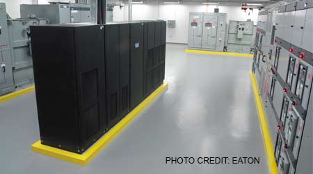
THIS IS NOT YOUR FATHER’S N+1 REDUNDANT UPS SYSTEM.
Traditional N+1 configurations required separate modules and a parallel cabinet with extensive field wiring between boxes. Now you can get from about 6kW up to 1.6MW in one UPS factory assembly or in one lineup and in a much smaller overall footprint.
The new, compact arrangement has many advantages, but one drawback is you cannot always change out a problematic redundant component without risk or shutdown of the entire system. That’s because you’re essentially dealing with one assembly. All of the key components may not be internally redundant as they are with traditional N+1 configurations, such as individual module inputs and dedicated battery strings per module. But if the cost and size of an N UPS is almost the same as that of an internally redundant N+1 UPS, the N+1 system is often the better choice. This is particularly true if the initial load will almost always be such that you can take advantage of the internal redundancy.
As an example, if an N UPS is rated at 90kW (one 90kW module) and an N+1 UPS is rated at 90kW (three 30kW modules), and your load will likely be less than 60kW, then the N+1 configuration will be the better choice. But if your load will likely be above 60kW, then the N configuration will be the better choice as it will include fewer failure points. N+1 systems include many common failure points, especially when considering input and output switchgear, automatic transfer switches, etc. These common or single failure points can be largely designed out with 2N designs or variations of 2N or multi-bus designs. Multi-bus configurations (especially those with redundant components in separate rooms) provide the highest reliability and allow for easier and lower-risk end-of-life replacement. It is very difficult to replace a single bus UPS system without a planned shutdown or risk of an unplanned shutdown.
Using internally redundant UPS systems allows for application of two systems to achieve 2(N+1) redundancy at a lower cost and size than most traditional N+1 configurations. If you’re up for the load balancing challenge, you can further reduce the amount of stranded capacity to achieve a high level of redundancy with three-to-make-two configurations, also known as 3N/2.
PREPARE TODAY FOR TOMORROW’S UPS BATTERIES.
Cabinetized VRLA (valve-regulated lead acid) batteries remain the mainstay and account for roughly 30 percent of the UPS total cost. Look out, however, for the impending lithium-ion revolution. You’re already carrying around lithium-ion batteries in your laptop and mobile phone. Your car may be propelled by an electric motor and lithium-ion batteries. And if lithium-ion doesn’t begin to take significant UPS market share soon, some other emerging battery technology may well do so.
Lithium-ion or other battery technology will likely require less space for the same runtime. Recharging time should be much faster and a common UPS failure mode — known as coup de fouet, or whiplash effect, which can result in UPS failure at the worst possible time, where the battery voltage drops deeply then recovers — should diminish, which may allow for shorter runtime requirements.
All of this should not only further bring down the cost and space requirements for new UPS equipment and further improve reliability, but may also affect replacement batteries for existing UPS systems. On larger UPS systems, batteries are often changed several times during the life of the UPS equipment. Therefore, when designing the space for UPS and battery equipment today with plans to add more UPS or more battery runtime in the future, you may not need to design and protect as much space for the future batteries.
UPS COOLING REQUIREMENTS ARE BECOMING DYNAMIC.
UPS systems, whether located inside the data center or (preferably) outside it, require reliable and often redundant cooling. UPS cooling has traditionally been sized based on a summation of worst-case conditions. These include full load and very low efficiency. But over-cooling UPS equipment is an increasing problem. UPS equipment that can experience large load changes or that can be operated in full online or in eco-modes (typically user-selectable) requires cooling that is much more dynamic than in the past. The UPS room cooling may need to reliably and automatically scale down from a worst-case 100 percent cooling function to as low as 5 percent. This dynamic cooling requirement means a simple, fully sized unit that is either 100 percent on or off probably won’t work.
Related Topics: