« Back to Facilities Management HVAC Category Home
Is "Free Cooling" Really Free?
July 14, 2016
- HVAC
By Robert Loflin
As businesses embrace environmental initiatives to save money, facility managers and building operators are feeling the pressure to increase building efficiency.
Free cooling, the process of allowing the building load to bypass mechanical cooling and exchange its heat with lower temperature outdoor air, is often positioned as an environmentally favorable approach that also helps save on costs.
Daikin recently simulated dry free cooling in two separate building environments representing light internal loads and high internal loads, to help determine the feasibility and value of free cooling in these settings. The simulation incorporated building data from several climates and geographical locations to factor in weather variation across the United States and modeled both integrated free cooling — where a water coil is directly mounted on an air cooled chiller — and standalone free cooling, where dry coolers are located separately from the air cooled chillers.
The results of the simulation suggest that free cooling cost benefits are often only realized in certain circumstances. Building type and climate dramatically impact the viability of free cooling, and in many cases, opting for standalone dry coolers rather than integrated free cooling may also positively impact cost savings.
Integrated Free Cooling vs Standalone Dry Coolers
This simulation focused on non-evaporative (dry) free cooling methods where the chilled water system directly exchanges heat through the use of an air-to-water heat exchanger, either integrated into an air-cooled chiller or through a standalone dry cooler. The two methods detailed here include: 1) integrated free cooling as part of the air-cooled chiller and 2) the use of separate dry coolers.
Integrated free cooling uses an additional coil, typically attached to the chiller on the outside of the primary condenser coil, to cool the process fluid using low temperature ambient air, as seen in Figure 1 below. Instead of mechanical cooling with refrigerant circulating through the condenser coil, the building process water is run through the integrated free cooling coil, which exchanges heat with the outdoor air to achieve either full or partial cooling of the building load before returning it to the building; in turn, this process requires less mechanical cooling.
Integrated coils also take up less space than a separate dry cooler, making them appealing to jobsites where space is limited. However, when not in free cooling mode, the integrated fluid coil causes air-flow restriction across the primary condenser refrigerant coil and therefore causes a derate on the chiller performance. The impact on chiller efficiency can be significant (in the range of 10-15 percent).
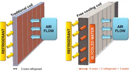 Figure 1: Integrated Chiller Free Cooling Concept
Dry coolers are a standalone fluid-to-air heat exchanger that receives the building cooling loop water directly, bypassing the chiller, and then exchange the heat with the outdoor air to cool the loop water before returning it to the building, as seen in Figure 2 below. To accomplish this, the three-way valve connecting the building cooling water loop to the chiller and fluid cooler closes off the line to the chiller allowing the building load to flow to the dry cooler directly. Therefore, using a separate dry cooler to perform free cooling does not restrict airflow across the condenser loop when not in free cooling mode since the dry cooler is located in a physically separate location from the chiller. This also allows the free cooling sizing to be independent of the chiller sizing and not limited by the chiller condenser surface area.
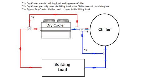
Figure 2: Dry Cooler Typical Piping in Series
Both of these types of free cooling applications can use less energy than a chiller-only system at low ambient conditions where free cooling is viable, lowering energy use and operational costs during those times. The example below investigates energy consumption and operating cost of running a 300-ton air-cooled screw chiller with and without integrated free cooling, and with separate dry coolers.
This simulation compared applying integrated free cooling, stand-alone free cooling, or no free cooling for two applications, a hospital and a data center.
The hospital model represents a building with fairly light internal loads, whereas the data center model represents high internal loads. The difference in internal loads plays a large role in the analysis to determine the effectiveness of free cooling for each application
Simulating light internal loads
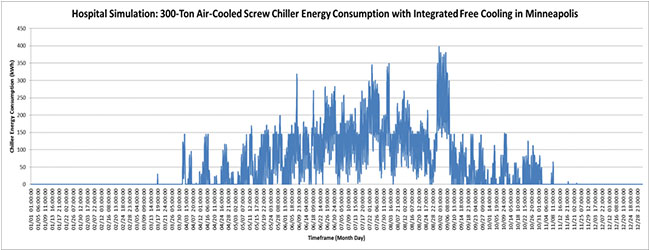
Figure 3: Hospital Simulation: 300-Ton Air-Cooled Screw Chiller Energy Consumption with Integrated Free Cooling in Minneapolis
Figure 3 shows the annual chiller energy consumption for the hospital model with integrated free cooling. It depicts the difference in chiller energy consumption between the cooler and warmer months. The cooler months are on the left and right side of the graph, and warmer months are towards the middle of the graph. A chiller will run most in warmer months when there is a cooling load on the building and temperatures are too warm for free cooling. There is not much potential for free cooling in the cooler months since the system load is low due to low internal cooling loads in the building. According to the usage graph, between the months of November and March we can see there is essentially no cooling load.
Figure 4 shows chiller energy consumption for the hospital simulation.
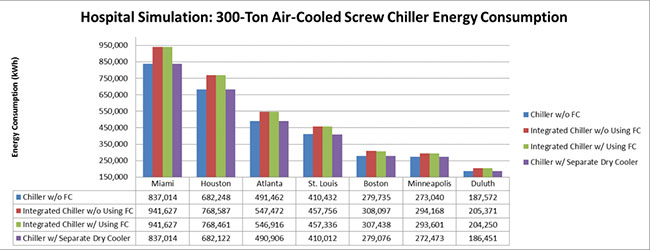
Figure 4: Hospital Simulation: 300-Ton Air-Cooled Screw Chiller Energy Consumption
Integrated Free Cooling Outcomes: Light Internal Loads
In the chart above (Figure 4), the blue bars represent a standard chiller without integrated free cooling. The red and green bars represent a chiller with an integrated free cooling coil. The purple bars represent a standard chiller with a separate dry cooler using free cooling as much as possible in that climate. The red bar assumes the integrated free cooling coil is not used at all (which gives us a worst case baseline of a chiller with the performance derate of the integrated coil but without the free cooling energy savings), whereas the green bar simulates using free cooling as much as possible in that climate. Comparing red to blue shows the performance derate on the chiller itself due to the added cooling coil; comparing red to green shows the benefit of integrated free cooling. Likewise, the blue to purple comparison depicts the benefit of using a separate dry cooler for free cooling. Noting that the blue bar is always lower than the green bar, we can quickly see that the chiller without integrated free cooling actually uses less energy. Furthermore, the purple bar is always lower than the blue bar suggesting the chiller with a separate dry cooler for free cooling does use slightly less energy.
The hospital simulation shows relatively few free cooling hours between the integrated chiller using free cooling and the same integrated chiller not using free cooling, as seen in the similarities between the red and green bars in Figure 4. The slight difference between the red and green bars increases further away from the warmer climates.
This suggests that free cooling requires colder climates to be effective, which is also seen in the difference between the blue and purple bars.
The difference between the blue and red bars demonstrates that a chiller without integrated free cooling consumes less energy annually than the same chiller with an integrated free cooling system. This is due to the restricted air flow across the condenser coils from the integrated free cooling system, forcing other chiller components to work harder to achieve the targeted cooling.
Because the hospital has such low cooling demand during the cold temperatures when free cooling is viable, the chiller performance derate from the integrated free cooling coil more than offsets any savings from free cooling. Chiller-integrated free cooling is not a good option for applications where low internal loads limit wintertime run hours.
In Figure 4, the blue bars (chiller without free cooling) show more energy consumption annually compared to the same chiller that uses a separate dry cooler for all locations except Miami, where warm temperatures limit free cooling usage. Some savings are realized with the separate dry cooler because unlike the integrated coil, it does not derate chiller performance, so even when the energy benefit is small, it is never offset by reduced chiller efficiency. However, the separate dry cooler energy savings only slightly offset the annual energy consumption.
Figure 5 depicts the savings associated with integrated free cooling for each hospital location.
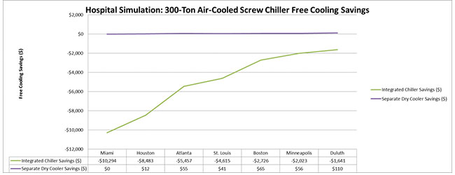
Figure 5: Hospital Simulation: 300-Ton Air-Cooled Screw Chiller Free Cooling Savings
Note that none of the locations experienced net savings throughout the year with the inclusion of integrated free cooling, as seen by how the green line never surpasses the $0 line on the y-axis. The chiller is less efficient because of reduced airflow across the condenser, and the integrated free cooling coil in the summer months more than offsets any savings in winter months due to low run hours.
Therefore, integrated free cooling is not a value-oriented option for this scenario.
Dry Cooler Outcomes: Light Internal Loads
The purple line in Figure 5 shows that all locations, except Miami, showed some net savings throughout the year when using a separate dry cooler to achieve free cooling. These savings are relatively small in comparison to the overall cost of the dry cooler and will not be a strong indicator for implementing a dry cooler for the hospital simulation due to an excessively long payback.
Conversely, the data center analysis tells a much different story. This is largely due to the data presented in Figure 6, which shows the annual chiller energy consumption for the data center model with integrated free cooling.
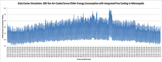
Figure 6: Data Center: 300-Ton Air-Cooled Screw Energy Consumption with Integrated Free Cooling in Minneapolis
Figure 6 shows that the chiller energy consumption throughout the year is more consistent compared to the hospital simulation. The cooler months are on the left and right side of the graph, whereas the warmer months are towards the middle of the graph. It should still be expected that the chiller will work harder in the warmer months to cool the building due to the extra external heat load on the building, which is evident in Figure 6. The more constant internal load in the data center simulation provides greater potential for free cooling in the cooler months.
Simulating High Internal Loads
Figure 7 shows energy consumption data for the data center simulation, which was conducted to simulate free cooling in a high internal load environment.
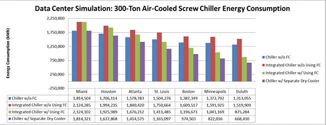
Figure 7: Data Center Simulation: 300-Ton Air-Cooled Screw Chiller Energy Consumption
The blue, red, green, and purple bars reflect the same chiller options used in the hospital simulation, but represent the data center simulation. The data center simulation showed considerably more free cooling hours compared to the hospital simulation, especially for the cooler climates.
Integrated Free Cooling Outcomes: High Internal Load
Per the hospital simulation, a chiller with an integrated coil that does not use the free cooling potential will consume more energy than a chiller without integrated free cooling. This trend is depicted in the varying heights of the red and blue bars, respectively, in Figure 7. St. Louis, Boston, Minneapolis, and Duluth were the only locations that showed energy savings when utilizing integrated free cooling in cooler months. The higher internal load in the colder months, as seen previously in Figure 6, provides greater availability for free cooling, thus leading to greater energy savings.
This suggests that integrated free cooling is a more plausible option for high internal load environments. Overall, the data center simulation benefits much more greatly from integrated free cooling in the cooler months and more than offsets the derate on chiller performance during the warmer months. The results lend credibility to using integrated free cooling systems for applications that have high wintertime cooling load run hours.
Figure 8 depicts the savings associated with integrated free cooling for each data center location.
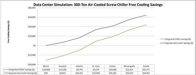
Figure 8: Data Center Simulation: 300-Ton Air-Cooled Screw Chiller Free Cooling Savings
It should be noted that the colder climates (Duluth, Minneapolis, Boston, and St. Louis) experienced considerable net savings throughout the year with the inclusion of integrated free cooling. The warmer climates (Miami, Houston, and Atlanta) experienced net losses and would not be good candidates for integrated free cooling applications.
Overall, integrated free cooling is only a sensible option when the wintertime building load is large enough and the climate cold enough to permit significant free cooling savings to offset the chiller performance penalty of the integrated coil.
Dry Cooling Outcomes: High Internal Load
Figure 8 also shows all of the locations experienced some net savings annually when using a separate dry cooler to achieve free cooling, with considerably more savings experienced in the cooler climates. Depending on cost of the dry cooler and location, using a dry cooler will likely show a beneficial payback in lieu of only using a chiller for annual cooling, with cooler climates experiencing more favorable paybacks.
Another added benefit is that separate dry coolers offer the same opportunity for free cooling to offset chiller run hours, and do not inhibit the chiller performance when the dry cooler is not in use since the dry cooler is physically separate from the chiller’s condenser coil.
This may allow a separate dry cooler to offer additional energy saving potential in systems like hospitals where the chiller performance derate of integrated free cooling may more than offset the energy savings opportunity of the integrated free cooling coil.
In summary, both climate and building type have a dramatic impact on the viability of free cooling using dry coils. In climates where the air is cold enough, and in applications where the number of wintertime run hours is great enough, both integrated coils and separate dry coolers can provide energy savings, but in all cases, energy savings with standalone dry coolers is greater due to the effects on summertime chiller performance. Building load profile is crucial in determining the viability of free cooling, as buildings with low wintertime loads will benefit less from any form of free cooling.
Methodology
This simulation modeled the impact of integrated free cooling on chiller efficiency and performance throughout the year using meteorological data available to evaluate each of the ASHRAE climate zones. This analysis used Daikin’s EnergyAnalyzer II software with its EnergyPlus version 8.1 simulation engine to model a 300-ton air-cooled screw chiller system. The methodology used the performance of a commercially available chiller with integrated free cooling to describe the efficiency derate information presented in this paper. Hourly data was pulled into the model pertaining to dry bulb temperature (T_DB), chiller load, and the electricity consumed by the chiller, whereas the total annual kWh for both chiller models was calculated. Some assumptions were used in this analysis, including:
• 100 percent free cooling was assumed at T_DB less than 37°F (2.78°C).
• 50 percent free cooling was assumed at T_DB from 37-42°F (2.78-5.56°C).
• Pump energy was excluded from the calculation.
• The same free cooling parameters assumed above were used for both the hospital and data center models for ease of comparison.
• Electricity rates used for both the hospital and data center models were $0.10/kWh. City-specific electricity rates were not included in this analysis.
The percentage of free cooling assumed was taken from the understanding that dry coolers can only meet full load capacity when outdoor dry bulb temperature is 7°F (3.89°C) lower than the desired leaving chilled water temperature. Assuming a normal 44°F (6.67°C) fluid temperature for comfort cooling, the outdoor temperature would have to be less than 37°F (2.78°C) to get full free cooling. Between 37-42°F (2.78-5.56°C) it was assumed that 50 percent free cooling was achievable for simplicity of simulation.
Robert Loflin is a chiller applications engineer for Daikin Applied.
Click here for more information on Facilitiesnet.com about chillers.


