Understanding Thermal Mass and HVAC Efficiency
For roofs and walls, especially, the amount of heat absorbed during conduction plays a huge role in how hard an HVAC system has to work to keep a building cool.
The types of materials that make up the other parts of the building envelope are as diverse and unique as buildings themselves. At the most basic level, heat is conducted through each material at a unique, specific rate known as a U-value. This term is dependent on not only the type of material in a construction but also the thickness of the material. For example, a 19-inch-thick wall of concrete has the same U-value as a steel-framed stucco wall with R-13 batt insulation in the cavity. However, when these two exterior walls are simulated over the course of an entire year, the energy model results will show that these identical U-values do not equate to identical performance for the same building. The results for the one-year simulation period will inevitably show that the two constructions conduct identical amounts of heat in and out of the building. But the results will also show that the concrete building’s HVAC system consumed nearly 57 percent less energy than the stud wall building. How is this possible when the heat transfer is the same?
It comes down to a matter of thermal mass.
Thermal mass is the amount of heat a wall absorbs during the process of conduction and is determined by the specific heat, density, and thickness of each layer in the wall’s construction. Specific heat represents the amount of energy (British thermal units, or BTUs) that it takes to raise the temperature of one pound of the wall by one degree. The specific heat of the concrete wall is only 15 percent greater than that of the stud wall. However, the concrete wall is nearly seven and a half times heavier per each square foot of horizontal surface area than the stud wall. The product of these two terms yields the construction’s thermal mass and demonstrates that the concrete wall absorbs nearly nine times more energy before its temperature increase by one degree. Heat is only transferred into the building when the interior surface of the wall becomes warmer than the ambient air temperature. Since the concrete wall absorbs nine times more energy than the stud wall, this temperature increase on the interior of the wall occurs well after the temperature outside has reached its peak. This means the heat load enters the space at night, allowing the HVAC system to be more efficient since it is operating in cooler ambient conditions. During days where large temperature swings occur, heat absorbed by the walls might never reach the interior of the building, thus providing even greater energy savings. This phenomenon can be seen in the graph below:
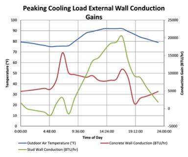
Energy modeling software calculates heat transfer on an iterative basis using the ASHRAE heat balance method, and accurately captures the thermal mass effect created by high-density constructions such as concrete masonry unit, brick, precast concrete, or even multiple layers of gypsum wall panels. This method uses the U-value, density, conductivity, and heat capacity at each calculation interval, ranging from two minutes to one hour depending on the software, to calculate the explicit heat transfer for an entire year. Traditional methods for calculating peak-loads use the radiant time series or transfer function method calculation procedures, which do not calculate heat transfer in an iterative manner. They instead rely on assumptions and pre-determined coefficients to simplify the calculation process, which cannot accurately capture the time-delay effect caused by increased thermal mass.
Roofs: Size Matters
A building’s roof receives more direct exposure to solar radiation than any other component of the building envelope. When analyzing a building’s roof, is it important to compare its surface area to the surface area of the other components of the building envelope. It is common in single story buildings to have a total roof area that exceeds the total wall area. In this case, upgrades to the roof are likely to yield a higher return on investment. Proper analysis of the roof also mandates proper modeling of the interior of the building. Buildings that have an attic or unconditioned areas between the roof and the room’s internal ceiling will experience a time delay effect in the rate of heat transfer since the large quantities of air in these spaces can also produce noticeable thermal mass effects, which can be properly analyzed and accounted for using energy modeling. Different combinations of roof or internal ceiling insulation can be simulated to determine the best method to minimize the annual load the roof imparts on the HVAC system.
How to Conduct a Proper Envelope Analysis
Energy modeling offers the chance to understand how a building envelope works with the HVAC system. This is in stark contrast to peak load calculation methods, which are better suited to determine how the HVAC system must perform to mitigate the effects generated by the building envelope.
In order to ensure that a building’s envelope works with the HVAC system in the most effective manner, the design team must work together to develop the project goals and constraints. The budget is typically the first constraint that can be used to narrow the options available to optimize the building envelope. Proposed materials and constructions can be eliminated from analysis based on cost. Aesthetics provide a range of materials that will be considered for a building’s envelope. Additionally, the longevity of the construction is an important consideration to help narrow the types of material choices.
Once a range of designs is selected, an energy model can be created to individually assess the performance of each construction. The quality of the results relies on the energy model being constructed to accurately reflect the proposed design’s geometry, occupancy loads, internal heat gains, and the intended schedule of use for the entire building. This model is simulated over the course of a full year using the weather data appropriate for the building’s location. This process makes it possible to understand how each building component contributes to the HVAC system’s overall energy consumption. Results can be evaluated strictly on the initial costs and savings or by more rigorous life-cycle cost analysis methods. Although all buildings are unique, energy modeling analysis allows a design team to consistently and accurately provide a specific solution to maximize the synergy between a building’s envelope and its HVAC system.
Miles Martschink, Jr., P.E., a project engineer with RMF Engineering, is an experienced mechanical engineer who routinely uses energy modeling techniques to support the analysis and design of mechanical systems for commercial, academic, laboratory, and athletic facilities. He has utilized energy simulations to create detailed heating and cooling load calculations, life cycle cost analyses, as well as for LEED Energy and Atmosphere credits.
Email comments and questions to edward.sullivan@tradepress.com.
Related Topics: