Retrocommissioning: Gathering Available Building Data
Before testing any equipment, inspectors should determine if the data is correct and has been verified. The next step is to begin testing procedures.
The next step in the retrocommissioning process is to gather all available data on the building, its systems and components, and the materials that make it up. Sources for this information includes prints, documents and manuals related to the building.
The essential plans include: original drawings, such as the architectural floor plan and roof plan; as-built drawings; specifications; HVAC drawings and schedules; electrical-system prints showing equipment; equipment submittals, and operations and maintenance manuals.
Key data on the building itself includes; its type, such as office or school; square feet; the year of construction and any renovations; building schedules; the number of occupants; results of surveys of building occupants of building; gas and electric utility billing information for last 12 months; and data from data loggers to produce a baseline.
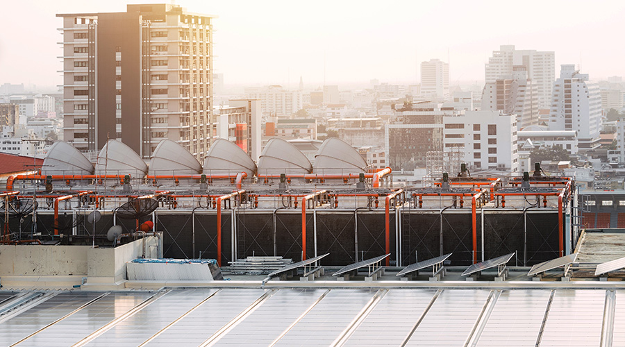
Equipment information data includes pump and fan curves, sequence of operations, control diagrams, system schematics, previous testing and balancing reports, and previous commissioning reports.
Data gathering also should include notes on conditions observed in the facility. Take airflow readings in each room and determine if the room is positive or negative pressure. Take temperature readings in each room. Get above the ceiling to look at ductwork and piping. Are any leaks visible? Are ducts still connected? Are VAVs or coils plugged?
Open every access panel to look at coils, fire dampers and other components. Are there leaks in the plumbing fixtures? Are faucets left running?
In the mechanical room, obtain nameplate information, such as equipment, manufacturer, model number, serial number and all capacities. Walk down and test each system down, and do line flow diagrams of these systems.
Before testing, the inspector should determine if the equipment label information is accurate. Using walkie talkies, station a team member at the equipment and another team member at the wall switch. Activate the on switch for the component, and observe if the equipment being tested responds properly. Once all equipment and switches have been verified, label all components correctly. Then repeat the same process at the breaker panel and the disconnect switch.
Testing, testing
Once an inspector has thoroughly verified equipment, components and disconnects, the next step is to begin test procedures to measure items such as cubic feet per minute (CFM), gallons per minute (GPM), static pressure, temperature, amp draw, and voltage. Then compare test results with original specifications, submittals, drawings, etc., to uncover discrepancies between the original design and actual performance.
Using guidelines from accepted industry standards such as ASHRAE, the inspector should perform preliminary calculations of required airflows to determine if current airflows are adequate or excessive. Using the information gathered, prepare a simple one-line airflow diagram showing HVAC equipment distribution of air in and air out, room and building pressures, identifying process equipment with values. The flow diagram should include notes on any discrepancies.
Flow diagrams can be simple or complex, depending on the building use and the manager’s expectations. By using a flow diagram, the manager can easily see the flow rates, determine whether an area is positive or negative, and identify areas that need addressed.
The inspector als should prepare a flow diagram for water use. Facilities have faucets and toilets that run continually and valves that leak. Water costs money, and organizations have to pay to bring water into the building and pay again for sewer charges when it leaves. A water in/water out flow diagram can help managers determine the amount of money the facility will save by doing repairs.
To compile the diagram, the inspector should go throughout the building, following water piping, counting the number of plumbing fixtures, type of fixtures, and GPM used, and documenting leaks and other water-waste issues. Obtain occupant loads and schedule, as well as utility costs.
The inspector also should look for uninsulated piping and record the pipe size and length. Utilities often give cash incentives for insulating uninsulated pipes.
The final step is to calculate water use and potential savings, then develop water-conservation measures managers and their staffs can put in place.
Related Topics: