Using CFD Analysis to Prevent HVAC Equipment Oversizing
Understand these best practices in using CFD to achieve high-performance, energy efficient HVAC systems.
What do complex spaces in buildings have in common with Formula 1 race cars, America’s Cup yachts, spaceships, and jet fighters? Increasingly, it may be that all have the opportunity to use computational fluid dynamics (CFD) to optimize design of complex architectural spaces.
For the majority of its life, CFD has been synonymous with the design of the most expensive, fastest, and highest performing human creations of human beings. Through the use of fluid dynamics equations and ever-increasing computing power, complex simulations have been performed to push the boundaries in both sport and science.
Today, CFD has been refined and perfected to a point where it can be delivered in a user-friendly manner that makes the tools accessible to a much wider audience. In the past, CFD analysis was only considered for use in the design of commercial buildings when the success or failure of a system’s performance could impact the life and safety of the building’s occupants, such as operating rooms, science labs, and the design of smoke evacuation systems, as well as in data centers. In today’s world, CFD can be used to aid more commonplace design in commercial buildings and help to reduce energy consumption and improve overall building performance.
High-performance buildings are synonymous with high-performance architectural and engineering design. The design of energy efficient HVAC systems has been greatly enhanced through the use of energy modeling, which allows a simulation of the building, weather, and internal conditions over an entire year. This holistic approach greatly aids in macro-level decision-making for HVAC systems; however, it has its limitations when it comes to optimizing spaces with unique architectural features.
All HVAC load calculations are based on the assumption that the space, or thermal zone, can be modeled with the air being well mixed. This assumes that the temperature of the air is uniform throughout the zone (ASHRAE, 2017). Under this assumption, common features of air distribution — such as stratification, thermal buoyancy, and convection currents — are all disregarded in even the most accurate load calculations. But complex architecture can create situations where “best practice” assumptions for airflow no longer apply. A simple analysis can show how CFD can reduce the overall cooling demand by optimizing air distribution in a space.
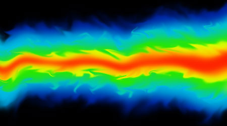
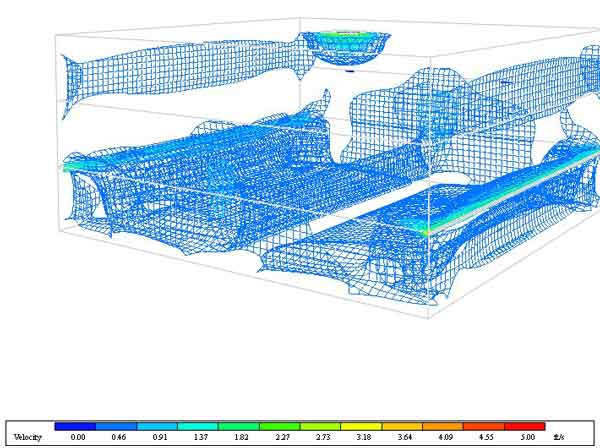
FIGURE 1: Non-isothermal CFD analysis of a 30-foot tall space
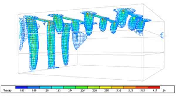
Figure 1 is an air velocity distribution map for a 30-foot-tall space with a 60-foot by 60-foot square floor plan. This single-room building has one south facing wall that is constructed entirely of glass. The space has been given a typical ceiling-supply, ceiling-return air distribution layout using linear slot diffusers with a manufacturer’s published throw of 31 feet with a 50 feet per minute jet velocity. The space has been stratified into three 10-foot-high zones, with the top two zones being unconditioned and the lowest zone requiring 8,280 CFM to maintain a temperature of 75 degrees F in the space.
FIGURE 2: Ceiling-mounted diffusers — temperature distribution
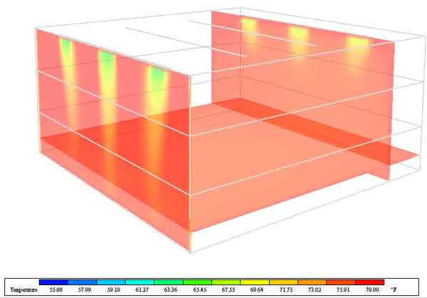
These assumptions should deliver a system capable of maintaining the space temperature; however, as can be seen in Figure 2, energy modeling shows that during peak cooling conditions the occupied portion of the space has a temperature of 78 degrees F. The reason is that the manufacturer’s published data for the air device’s throw assumes isothermal conditions, in which the temperature is constant and homogenous throughout the system, but Figure 1 shows that the air leaving the diffusers in the middle of the building barely makes it 10 feet downwards until the jet loses almost all velocity. The leftmost diffusers in Figure 1 do reach down into the occupied space; however, this is due to the tendency of air to cling to an adjacent flat surface (known as the Coandă effect). The air is entrained, allowing a region of lower pressure. Figure 2 shows that the air leaving these same diffusers absorbs the heat from the south-facing windows and, by the time the air reaches the occupied region of the space, it is too warm to perform any cooling. At this point in the analysis, it is clear that the assumptions that were used to make this design were inappropriately applied.
CFD analysis can be used to ensure mistakes like these do not go unnoticed.
CFD Analysis Best Practices
The majority of CFD analysis software for use in commercial building design performs an analysis of a single space for an instance in time. Each variable being analyzed (typically velocity, temperature, pressure, viscosity, and turbulence) is simulated and compared against the others over multiple iterations. The goal is to perform enough iterations to show a consistent pattern.
The more iterations that are performed, the more confidence that can be gained, but even with modern computer power the calculations take time so it is important to exercise sound engineering judgment that a stable simulation has been produced before utilizing the results.
It is not practical, or even necessary, to perform a CFD analysis of every space in a building. In order to effectively utilize CFD analysis in HVAC design, the first step is to determine where the standard “best practice” assumptions of airflow in a space no longer apply, such as atriums, spaces with irregular geometry (e.g., curved walls), and spaces with large windows. With the endless variations in building architecture and climate, a good rule of thumb is that CFD should be used in any instance where the engineer wants to take advantage of high-throw diffusers or stratification.
A good place to start with any analysis is to simulate the space during the peak heating and peak cooling conditions. If a clear pattern is not emerging, then the engineer should analyze more part load conditions. Strict adherence to the scientific method is key to success; when the engineer receives a favorable result, enough simulations need to be performed in an attempt to disprove the result. Performing simulations with different exterior conditions while holding the interior conditions constant is the most effective methodology to pinpoint the weakness in the design. If multiple systems or air distribution layouts are to be analyzed, all efforts should be made to maintain the same space and supply air temperatures across all simulations to ensure that the only variable being assessed is airflow.
FIGURE 3: Wall-mounted diffusers: velocity map
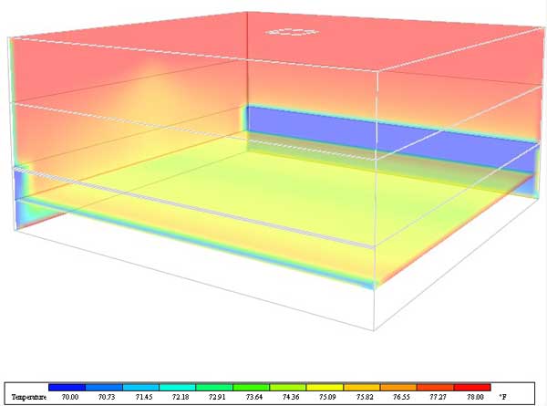
The lessons learned from the previous example can be used to optimize the system to deliver the desired performance. By mounting the supply diffuser along the east- and west-facing walls, the HVAC system can actively stratify the space and ensure that only the bottom third is conditioned. The effect of this layout can be seen in Figure 3, as cold air is thrown towards the middle of the space and falls to the floor when it loses velocity. The air adjacent to exterior walls is inherently warmer than the air in the middle of the room, as it is absorbing the heat being conducted into the building. This warmer air naturally rises towards the ceiling where it is extracted from the space by the central, ceiling-mounted return-air grille. This layout utilizes stratification to enhance the performance of the HVAC system, which results in a system that is able to maintain the desired spaced temperature of 75 degrees F while utilizing 27 percent less supply air. Figure 4 details the even temperature distribution in the occupied area and the pronounced stratification that is a result of a well-engineered air distribution layout.
FIGURE 4: Wall-mounted diffusers: temperature distribution
Energy-efficient buildings are a necessity for a sustainable future. HVAC design has relied on a vast array of assumptions to ensure the systems could be designed in a timely manner and perform as required. The power of CFD analysis is that engineers now have a means to validate “out-of-the-box” ideas which allows an HVAC system to reach the next level of efficiency by replacing the assumptions of old with project specific facts. Using CFD analysis to sculpt HVAC design in complex spaces makes it possible to remove unnecessary safety factors and redundancies that ultimately lower the overall efficiency of a system.
Miles Martschink, Jr. (miles.martschink@rmf.com), PE, a project engineer with RMF Engineering, is an experienced mechanical engineer who routinely uses energy modeling techniques to support the analysis and design of mechanical systems for commercial, academic, laboratory and athletic facilities. He has utilized energy simulations to create detailed heating and cooling load calculations, life cycle cost analyses, and to satisfy LEED Energy and Atmosphere credits.
(NOTE: The assumptions in load calculations were pulled from the 2017 ASHRAE Handbook - Fundamentals, Inch-Pound Edition.)
Related Topics: