« Return to FMDAA entries

Medical University of South Carolina
CATEGORY: Renovations and Retrofits
Medical University Hospital Authority
Sabin Street Energy Plant
UH/CH Infrastructure Relocation Project.
Overview
1. Project Description
MISSION
In August 2010, the Medical University of South Carolina (MUSC), Medical University Hospital Authority (MUHA) commissioned a mitigation study to be produced by a team of architects and engineers to evaluate the potential threat and risk to the normal power, emergency power, steam, chilled water, medical gas and other related infrastructure systems and equipment at its university and children’s hospital's facilities. These concerns were generated from past experience with tropical storm surge and regional flooding in and around the two Hospitals. These experiences produced flooding that resulted in close calls of near total system failure. The evaluation included a survey of current system configurations, locations of vital equipment components and the identification of those components that are most threatened by the events. The final deliverable was to provide MUHA with proposals for eliminating and or mitigating identified risks.
The results of the mitigation study were published and reported to the MUHA on November 11, 2010 and documented the various services, equipment and systems and the serious potential risks to these system. The study identified recommendations to eliminate or at least mitigate these risks. The study concluded that the creation of a vertical building expansion with the lowest levels of the facility above the storm surge levels and the relocation of infrastructure equipment and systems to these elevated areas would greatly reduce the threat and risk of flooding and would be the best solution for continued operations of vital infrastructure systems during and after such events.
To fully understand what a significant flood event would mean for the hospital facility, the Architectural and Engineering team presented the following question:
"What utility and other infrastructure systems would the University Hospital and Children's Hospital lose as a result of a flood event?"
The report indicated that both hospitals would experience total loss of both normal and emergency power systems, boilers and condensate pumping systems, chilled water and medical gas systems as well as other important infrastructure equipment and systems. The environment that Hospital Administrators, Doctors, Clinicians, and Hospital support personnel would be subjected to if these system were lost would be catastrophic to the function and operation of the Hospital. These service losses would mean:
- No electrical power for lighting, and medical equipment operation.
- No steam for reheating, dehumidification, sterilzation, and cooking.
- Loss of domestic cold and hot water for hand washing, toilet flushing, cleaning and cooking.
- Loss of fire pump services for fire safety.
- Loss of medical air and vacuum systems for patient care.
The losses of the infrastructure systems indicated in this report and the subsequent effects to the hospitals would be devastating. Depending on both the severity of the storm or surge and subsequent damage to the infrastructure of the hospital's normal power electrical utility supplier, South Carolina Electric and Gas (SCE&G), it was anticipated that restoration of normal power may take several weeks. Even if the utility recovery was made sooner the recovery time for the hospital to repair or replace damaged equipment to normal and emergency power distribution equipment, boilers, chillers would be relative to the ability of engineer design, vendors, manufacturers, and suppliers to order, ship, and deliver equipment and materials for the systems to be replaced and/or installed.
Additional time would be required for the contractors to install, test and start the new systems. Preliminary schedules would indicate some of the first systems could be started within approximately nine months. Occupation of the facility though could not occur until DHEC inspections of renovated areas and systems were completed and areas cleaned. This would add approximately three to four months to the process. Little did the study team know these types of scenarios would play out for real in October of 2012 when Hurricane Sandy impacted the New Jersey and New York area with eerily similar results to the area’s hospital power, water and mechanical systems.
The mitigation study’s research, observations, and insight provided recommendations to significantly reduce the flood threat and risk to the Hospital facilities infrastructure. The ability of the hospital to maintain operations throughout a tropical storm event would be a tremendous advantage to the Charleston area as a shelter, emergency response center and first aid station. Avoiding the threat and risk of the loss of emergency power would also allow systems on that power source to remain active and operational until normal power could be restored to the hospital. This capability would result in the facility’s ability to provide vital care for the region during such an event and significant time savings in the re-opening of the facilities full services as a hospital. The ability to maintain operations through a flood event would potentially save hundreds of lives in a weather emergency.
VISION
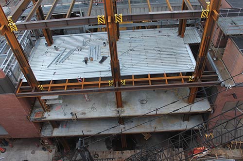
When surveying the location of the existing generator, boiler and other infrastructure equipment a small space footprint was identified that was adjacent to both the children’s hospital and university hospital that was occupied as the facilities loading dock. This area afforded and ideal location to capture the interconnecting electrical, steam, medical gas and domestic water pumping and piping systems. The design/owner team was challenged to develop a building that would occupy a footprint of only 36’-4" by 78'-9". A stacking plan was developed and illustrated the ground floor would be a renewed loading dock, trash dumpster area that the space was originally used for. The second level would house the medical gas equipment, domestic water and cooling tower pumps. The third level was designated for the electrical switchgear area for the generators. The fourth level was designated for the steam boilers and condensate systems. The fifth level would house the emergency power generators. The sixth level or roof would be fitted with elevated steel to support both new cooling towers and the generator remote radiators. Due to the size and needs of the equipment, some floor to floor elevations would vary in height from twelve feet at the pump room to twenty four feet at the boiler room. The overall height of the structure was designed at eighty four feet from grade to the cooling tower level. There is an additional height of screen wall as the cooling towers are enclosed with a perimeter screen to conceal them and was laterally supported by the steel frame to compensate for wind loading to the building.
Much of the exterior wall was planned for light weight metal panels with louvers for ventilation. To increase the square feet of the building the 5th and 6th floors were enlarged. This enlarged plan cantilevers to the east and west over fifty feet, over the existing buildings. This is a very large cantilever and there was difficulty in getting a structural solution for this option. Special steel moment frames were utilized as the lateral load system in the east-west direction while special eccentric braced frames were utilized in the north south direction at the outermost frame lines.
The floor structure was comprised of a 6 inch light weight concrete slab on composite metal deck. The slab bears on closely spaced steel beams designed to support the heavy weights of the equipment as supplied by the engineer team. The beams span to steel girders supported by steel columns. The entire building is pile supported.
Special Design Considerations:
The building is designed as an essential facility since it provides mechanical and electrical service to the university and children’s hospitals which are intended to remain operational after any type of natural disaster. The classification as an essential facility causes an increase in the importance factor for the wind and seismic loadings. Also, since the equipment in the building is permanent and of significant weight, the dead load of all equipment is included in the seismic load calculations. Another special consideration is the lateral movement that occurs within this building and the adjacent existing buildings during a wind or seismic event. This lateral drift must be considered where floor to floor passage is desirable between buildings. A structural expansion joint is required between buildings to allow the differential lateral movement. The total lateral movement between buildings had to be more thoroughly evaluated due to the movement of the existing buildings. The movement in the new building is currently estimated at seven (7) inches in any direction. This amount will be combined with the movement of the existing buildings for a total amount of clearance required. Any access corridors between the new and existing buildings will require a floor expansion joint capable of accommodating the total movement.
Flood Tolerant:
The equipment will be located above the existing FEMA Maximum 100 Year Wave Crest. While the utility supplier (SCE&G) equipment will still be effected by flooding and commercial power would be interrupted, the new service equipment will be above the flood level; and therefore, will not be damaged. The undamaged service equipment would allow commercial power to be restored when made available by SCE&G. The new equipment will be sized to include the existing demand plus future growth. The new emergency generators will included new day tanks assemblies and will connect to the existing fuel tank installation.
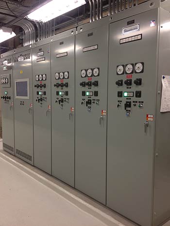
Code Compliant:
The new system complies with NEC Article 517 - Health Care Facilities. Three distinct branches of emergency power will be provided. The new equipment and installation will meet IBC seismic requirements.
Reliable:
The redundant N+1 arrangement of generators and unit substations will eliminate most of the single-points-of-failure. Selective coordination of the system overcurrent protective devices will control the system such that the device closest to a fault trips thus minimizing power interruptions to the unaffected portions of the system.
Robust:
The redundant arrangement of unit substation feeders protects from future crisis projects. For instance, if a transformer on the A-side of the new life safety branch unit substation fails a tie breaker can be closed from the B-side to restore power to the life safety branch. The damaged transformer can be isolated and replaced without significant and expensive temporary measures being put in place.
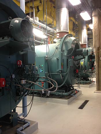
Efficient:
Compared to the existing equipment, the new equipment will be approximately ten 10 percent more efficient.
Cleaner:
Compared to the existing equipment, the new equipment will deliver approximately 80 percent fewer emissions.
Safer:
The new system can be sectionalized to isolate damaged equipment. Once isolated, damaged equipment can safety be repaired or replaced. All new equipment will be labeled in accordance with current NFPA arc-flash labeling practices. The arc-flash labeling will enable workers to select personnel protective equipment sufficient to safely perform the work.
Enhancing Staff Productivity
The existing previous emergency power system had seven generators in three separate plants. The plants were located in different buildings and spaces. The manpower required to operate and test the new system will be reduced because the new system serves both hospitals from a single location. The new system will include the equipment necessary to load-bank test the system using a bus duct isolated by a breaker. This will allow easy connection to either a portable load bank or it can be used to connect a temporary generator to the system.
Smarter:
The new electrical system will include a supervisory control and data acquisition (SCADA) System that will provide local and remote monitoring, simulation for training purposes, historical load trending, and automatic JCAHO reporting, load monitoring and management.
The new cooling tower system will utilized Trane Tracer Summit Chiller control management to provide local and remote monitoring, historical load trending and alarm monitoring and load monitoring and management.
Variable speed domestic water pumping will optimize energy cost by turning down pumps during low loads based on flow and pressure.
Medical air and medical vacuum pump staging controlled by load management based on volume and pressure needs.
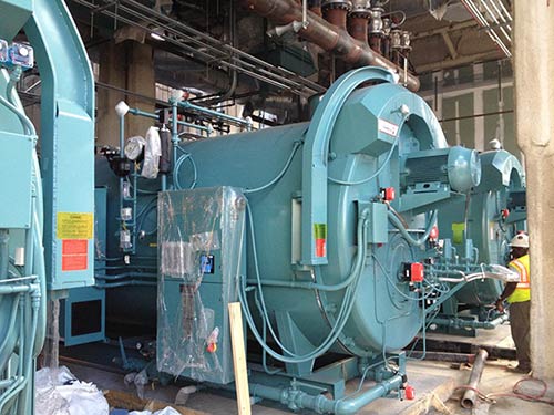
Steam Boiler burner management with O2 trim manages fire rate efficiency. A master plant controller optimizes boiler operations based on load profile and rotates equipment lead and lag equipment to balance equipment runtimes.
Johnson Control Metasys building automation integration with all equipment to provide remote monitoring of entire energy plant operations and alarms.
GOAL:
The MUHA Medical Center has 709 licensed beds and serves over 32,000 inpatient admissions and over 730,000 outpatients annually and is the only level one trauma center for the area. The loss of any part of all these services for the area would be significant blow to the healthcare services for these patients.
The study clearly demonstrated the risks that the medical center faces and that those risks could realistically put the medical center in a poor position to be unable to serve the needs patients, visitors and staff if any one of these key infrastructure systems failed. It was clear that the MUHA must eliminate or at least significantly mitigate the risk to its vital infrastructure from flooding. In addition the study also concluded that much of equipment at risk was near or over its expected service life. Much of the equipment was also of low efficiency and not integrated with the building automation system. The systems were fragmented and located in multiple equipment rooms throughout the patient care areas serving portions of the facility thus requiring more maintenance on multiple smaller systems rather than consolidated in a central plant.
Based on these findings the team concluded that the goal was not only to harden the infrastructure ability to withstand severe weather flooding, but also modernize and consolidate systems while simultaneously improving redundancy and demonstrating a reduction in operational expense.
TEAM APPROACH
The team members felt it was in the best interest of the medical center to begin risk mitigation as soon as possible and develop several fast track enabling projects while design and development continued on the energy plant itself. The design/owner team planned the project to be roll out into five phases of construction. This enabled an earlier start in construction and coordinate related infrastructure connections of related systems.
1. Preplanning, development, and implementation of stages
Phase 1: Refrigeration Equipment Relocation
Phase one was the relocation the hospital’s dietary refrigeration condenser equipment that was located in the footprint of the new building. Multiple air cooled condenser units were mounted on racks along the outer wall of the area of construction. This equipment was also very old and was in need of replacement. The equipment was redesigned, modernized and relocated.
Phase 2: Electrical Feeder Relocation
The next element that had to be moved was the university and children’s hospital medium voltage normal power feeders. These feeders ran directly through the building site and would not be accessible once the building was constructed. New feeders were rerouted around the construction site and connected to the hospitals.
Phase 3: Nitrous Oxide Storage and Manifold and New Loading Dock Construction
Since the site selected to construct the new infrastructure plant was at one of the key loading dock facilities, the problem of how deliveries would be managed during the construction phase. A location was found to create a small loading dock outside the construction area, but this space was occupied by the hospitals Nitrous Oxide manifold room. The nitrous oxide system was relocated to the existing manifold tank room and both elements of work were combined and coordinated in this phase.
Phase 4: Utility Relocation and Temporary Loading Dock Construction
The next phase was the relocation of the hospitals sanitary and storm systems that ran through the construction site. This included the replacement of a very old and very undersized sanitary grease trap. The manhole systems were placed and coordinated water outage with the clinical operation made the final connections to the building.
Phase 5: Construction of the Building and Infrastructure Systems
After the completion of the enabling projects the construction of the building for the new equipment began. The Construction of the new plant began on Sept 17, 2012.
2. Communication on project development and status
In the enabling phases, the team met weekly to discuss work in progress of the phase underway. These working sessions were geared to directly resolve RFI’s by the contractors, design revisions, submittals approvals and any barriers that needed to be resolved.Scheduling of buildings system outages was also a key element to coordinate with the Hospital team.
After the construction meetings the team would continue to transition to a design progress and planning meeting for the final building phase. This was helpful on team member’s schedules and provided helpful insight in filling gaps in scope between the phases.
Once the building phase began the wwner, A/E and contractor team continued on a weekly schedule of informal working sessions to perform the similar functions. Once monthly a formal meeting would include additional Hospital leadership and administrative team members from the hospital. These formal meetings also included some working sessions, but included budget and overall building schedule presentations.
3. Meeting the organizations strategic and master plans
The OAC team worked throughout the project to ensure the project strategic objectives were being met. It was the full team’s responsibility to review and comment during the weekly meetings to ensure any system or building modification still met the needs of the project, both in value, performance and schedule.
4. Time Management
This was a fast paced project, it was key for the team to keep on track of the schedule milestones. The team again focused on both short and long term milestones. This was significant especially where new systems were ready to start and old systems ready to be deactivated.
5. Financial Considerations for completing the project on time
MUHA was able to apply and be awarded two Federal Emergency Management, Pre-Disaster Mitigation Grants from FEMA. These grants awarded the medical center nearly $6,000,000. However, there was a limited timetable to complete the project to receive the grant dollars so completion had to stay on track. Though the medical center was fully committed to fund the project the grants relieved some of the financial burden.
6. Commissioning
Full Commissioning was performed on all generators, paralleling gear, ATS switches, and Medical gas equipment.
7. Supporting the needs of the Community
The MUHA medical center has 709 licensed beds and serves over 32,000 inpatient admissions and over 730,000 outpatients annually and is the only Level one trauma center for the area. The loss of any part of all these services for the area would be significant blow to the healthcare services for these patients.
8. Enhancing staff productivity.
Savings in both operation and maintenance were engineered into the project. The most significant of these was the reduction of three standalone generator plants and two separate Medical gas equipment systems that were located in different buildings, each requiring management, and maintenance and testing were consolidated into single systems. This operational efficiency can be measured in several as follows:
- Man-hour savings for generator testing = 342 annually
- Man-hour savings for generator system inspections= 260 annually
- Man-hour savings for medical gas service = 520 annually
9. Maintaining facility performance during the various project phases
Maintaining services while transferring connected loads to the new energy plant was a huge challenge. The design team made every effort to reduce the impact of final connection of hospital loads to a minimum. Effort resulted in a minimum number of mechanical and electrical utility outages for the hospital. This effort resulted in zero clinical lost time incidents do to the project.
10. Support the Organizational realignment
There were no organization realignment goals for this project other than an overall accomplishment of improving the productivity and cost of operation the new energy plant was able to achieve.
11. Unique about delivery method
Because the project rolled out in multiple phases the owner took advantages of multiple procurement and delivery methods that best suited the activities. The smaller enabling projects were essentially contracted directly by the hospital and managed internally with its own project manager. The final construction of the new plant was delivered by a general contractor with a GMP.
Team Challenges
Key challenges included the enabling projects that hindered the ability to build on the site. As state they included:
Refrigeration Equipment relocation.
The dietary equipment relocation challenged the team to maintain amble refrigeration and freezer capacity for food for the hospital while relocating and upgrading all the walk in refrigeration/Freezer equipment. Food was transferred to truck refrigeration units then back as the equipment was installed and started.
Electrical Feeder Relocation
Both the university and children’s hospital medium voltage normal power feeders ran directly through the building site and would not be accessible once the building was constructed. Careful planning to de-energize one set of electrical feeders and relocate new feeders while running on the secondary feeder was undertaken to accomplish this task. Once in place, the new feeder was energized and the same relocation of the secondary feeders was accomplished. Again this process resulted in clearing the building site and upgrading the existing incoming electrical feeders.
Nitrous Oxide storage and manifold and New Loading dock construction
The construction of the new plant caused the complete shutdown of one of the key loading dock facilities for the hospital. The challenge to keep deliveries flowing in the hospitals would have to be managed during the construction phase. There was a location found that was suitable to construct a small receiving area that could be used as an additional loading facility. The problem was it presently housed the nitrous oxide manifold for the hospital. Since the other medical gases were housed in another space it was a good plan to relocate the nitrous oxide with the other medical gas manifold room and create a new small loading facility with a power lift to relieve the loss of the loading dock while the project moved forward. This secondary loading dock remains in operation even after the project as it provides a needed additional loading service for the facility.
Utility Relocation and Temporary loading Dock construction.
The next phase was the relocation of the hospitals sanitary and storm systems that ran through the construction site. This included the replacement of a very old and very undersized sanitary grease trap. The design of the new grease trap resulted in a size and mass that was so large the system had to be pile supported due to the poor soil conditions in Charleston. The sanitary and storm relocation also included necessary manholes that would be needed to tie in the new building as well. The grease trap and new sanitary lines were installed outside the building footprint and routed to the Hospital outfall point. A coordinated water outage allowed for a quick removal and connection to the new system.
Construction of the Building and Infrastructure Systems
The construction of the building and interconnecting the infrastructures had several key challenges to overcome. They included:
Small building Footprint and construction site:
As stated earlier the footprint of this building was extremely small and the construction lay down was virtually nonexistent. Careful planning to bring material in to the sight that was needed by the various contractors was critical to efficient work flow.
Pile construction:
The next challenge was pile driving. Since the soil conditions in Charleston, SC require any building to be pile supported, driving steel or concrete piles was a big concern. The job site was less than two hundred feet from operating suites in the Children’s hospital and about the same distance from the Intensive Care units in the University Hospital. Hammering piling posed a huge issue with patient care. A solution was developed by ADC engineering and the Lemoine Company to install a modified Auger drilled piling system that required only one pile per pile cap. This method significantly reduced the noise and vibration that would impact the patient care areas.
Final connection of utilities:
The actual construction of the systems within the new building could progress well and as each system was completed they were started and tested and commissioned for operation. After this the final connections to the hospital facilities had to be made. For most of the mechanical systems this was accomplished through well thought out design that paralleled the old and new systems so transferring to the new equipment was a matter of valve alignment.
The electrical final connections were more of a challenge. With the extensive system reconfiguration of three existing generator systems of different voltages to one system it was impossible to make the final connections without some shutdowns of critical power. This was achieved by an extensive survey of connected loads on each automatic transfer switch branch and a risk assessment and mitigation action plans to accomplish each shutdown and reconnection to the new energy plant. It is easy to understand how critical it was to understand the impact of disrupting emergency power in a hospital, even a disruption for a few seconds can have serious patient safety outcomes. This took a huge effort by the engineering team, MUHA clinical operations group, our disaster preparedness group and the facilities electrical shop as well as the project electrical contractor, each connection was meticulously planned and executed. The hospital instituted a HICS (Hospital Incident Command System) model to orchestrate each electrical transfer. The team created a playbook that detailed every aspect of the process to de-energize the old emergency power branch and re-energize the system on the new plant’s new automatic transfer switches and distribution. It took over fifteen separate electrical utility outage events to complete the entire switch over to the new plant. These complex and significant electrical utility outages resulted in zero lost time to clinical operations and zero negative patient safety outcomes.
Post occupancy/Post – Completion Evaluation
1. Explain the economic (and other benefits) that you expect to gain from your project. (Include statistics, benchmarks, and comparisons to previous practices, buildings, or infrastructure.)
Key improvements include the consolidations of the emergency generator system for the both the university and children’s hospitals. That consolidations reduced the number of standalone generator plants from three to one. As detailed above, this saves man-hours for routine testing and maintenance. The project also reduced the number of Automatic Transfer Switches from 23 to 16. Additionally, the old ATS switches were in multiple locations in the buildings. The new switches are in three locations. This saves time in testing ATS switches since technicians have fewer places to go to perform all the tests. Also, the documentation of generator and ATS tests was a long process with each generator and ATS having to have its own log for each tests, so consolidation has correspondingly also reduced the amount of documentation required. Consolidation of domestic water pumps reduced the pump units to maintain from six to three. Consolidation of Medical gas pumping systems reduced Vacuum pumps from six to four and medical air from six to three.
Breakdown of annual savings:
- Cost savings in technician labor = $31,416
- Cost savings in outsourced generator/ATS service and maintenance = $35,500
- Cost savings in outsourced medical gas equipment maintenance = $1,200
- Cost savings technician labor of domestic pumping = $896
- Cost savings from outsourced cooling tower maintenance = $6,720
- Total annual maintenance savings = $75,732
2. Provide written documentation that includes a minimum of six months post occupancy (or post completion) data demonstrating how the team achieved the desired outcomes in terms of:
a. Space efficiency
The consolidation of the generator plants and the development of the unit substation design put all of the key generator components in dedicated electrical spaces. This plan greatly improves the staff’s ability to monitor and maintain equipment without having to go to multiple locations.
b. Environmental awareness
The new equipment represents a ten percent overall improvement in efficiencies for less fuel consumption, and less fossil fuel emissions.
c. Flexibility of design
The design improved greatly the distribution of emergency power which allowed multiple path redundancy of power and the ability to service components of the medium and low voltage switchgear without disruptions. The steam system provided manifolded steam headers and condensate collection and pumping that gives service technicians an ease to take equipment off line without disruptions. Multi staged compressors for medical air and vacuum provided easy rotation of equipment and service without service disruptions. All mechanical equipment and systems have at least N+1 design plus above a 20-30 percent increase of capacity to allow future capacity for expansion.
A unique feature of the emergency power plant design allows for the complete isolation of the hospitals from our commercial power source and the ability to connect all normal and emergency loads to the generator plant. This feature is significant as it hospital the ability to run all equipment, including its HVAC equipment on emergency power if the outage of commercial power is significant. The buildings did not have any emergency power capacity for HVAC systems previously.
d. Projected vs. actual costs
The budgeted cost of this project including enabling projects was $40,500,000 and final cost reconciliation was $40,503,682. This represents less than a 1 percent cost overrun. The medical center received $6,000,000 of pre-disaster mitigation grant and reduced the overall project cost to $34,503,682.
e. General aesthetics
Though this is a back of the house type project the enclosed loading dock facility and the fact the new building masks a significant amount of roof mounted equipment the facility has had a significant aesthetic improvement and a cleaner environment for the trash service and loading areas.
f. Energy Efficiency
Overall a ten percent improvement in fuel consumption of natural gas and fuel oil for the steam equipment.
Actual Natural gas savings dekatherms degree day adjusted
| |
Total
|
Jan
|
Feb
|
Mar
|
Apr
|
May
|
June
|
|
2013- Old
|
79021
|
16320
|
16180
|
16808
|
15379
|
16236
|
13298
|
|
2014- New
|
76473
|
11919
|
12744
|
15460
|
12833
|
11922
|
11595
|
|
Savings
|
9.6%
|
|
|
|
|
|
|
In-house Participants
Ignacio Pla, Project Manager, Medical University Hospital Authority
David Dement, Director of Facilities, Medical University Hospital Authority
Additional Information
↑ Back to top