Issues Involved in Continuous Containment for BSL3s
Part 3 of a 4-part article on key issues in ensuring that renovated BSL3s meet current standards
The concept of continuous containment in high containment labs is important and not easy to accomplish. It involves a number of issues for facility managers, including quality of construction and the HVAC sequence of operation.
CONTINUOUS CONTAINMENT
Even when the infrastructure that supports a BSL3 is functioning well in normal operation, there is every expectation that it must also continue to function well during failure scenarios. The Biosafety in Microbiological and Biomedical Laboratories, 5th Edition (rev. 2009) or BMBL5 is explicit in its mandate not to allow pressure reversals under any operational circumstance, including failures. This means that no pressure-managed space can ever lose its directional airflow and push past a neutral condition.
If you think of circumstances such as fires that require first-responder access or loss of grid power/transition to generator power, this zero-tolerance policy is a challenge, especially in an existing building. Some key focuses and strategies that will help frame the facility manager’s thinking include:
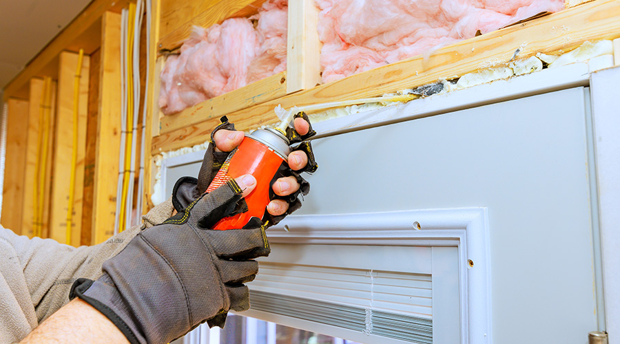
Quality of architectural constructions. Maintaining code and standard minimum pressure offsets at barriers, which require a demonstrated directional airflow, is largely a matter of building the “tightest” possible assemblies. In these situations, the paths for air to travel are highly limited in terms of area (e.g., door undercuts, dedicated ducted pathways), which will greatly reduce the air volumes required to meet the benchmark pressure offsets from an energy and balancing perspective, which is exactly what is desired.
Be aware, though, that ultra-tight constructions can also foster specific system performance issues. These issues can manifest themselves in moments of pressure reversal as system supply and exhaust fans ramp down in response to alarms and differential pressure forays that seem to defy trended airflow data provided by the building automation system.
The HVAC sequence of operation. The general logic for pressure-controlled HVAC zoning must be based on normal operations where a tracked flow offset or a room pressure differential is the mechanism by which directional airflow is maintained. Normal operation of the suite must obviously be described, but there also needs to be an accompanying series of “distress modes.” These will define the particular and orderly actions that each air control valve and piece of system equipment will take to maintain no greater than neutral pressure in the zone relative to an indexed baseline. These distress modes should include real-world scenarios akin to these examples and be as particular as possible:
• Loss of expected pressure set point in exhaust ductwork.
• Loss of expected pressure set point in supply ductwork.
• Indication that volumetric airflow in or out of the space (as measured at the zone by airflow measurement or room pressure) is at variance with that expected.
• Known loss of power under a condition when the generator is starting.
• Known loss of power under a condition when the generator is not starting.
Each distress mode must define a clear condition and then provide a sequential logic by which the system components react.
Related Topics: