Swing ATS and Catcher Redundancy Strategies
Part 5 of a 5-part article detailing the factors involved in deciding the level of redundancy for critical facilities.
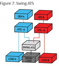
Similar to the 3N/2 redundant UPS configuration, a swing ATS can be used for cooling equipment arranged in groups of three to reduce stranded redundant cooling capacity from 100 percent to 50 percent. (See Figure 7.) Again, equal load groups of three work best for this application. For example, if 100 tons of cooling are needed, the A side can provide 50 tons, the B side 50 tons, and the swing ATS another 50 tons. Any single failure of a generator, ATS, switchboard, etc., will result in loss of only 50 tons. This is effectively a hybrid of parallel N+1 and 2N, providing reliability benefits similar to 2N, without resorting to a single parallel system and with less stranded capacity. The challenge is with managing the load balance such that no single failover scenario results in overload of redundant equipment. Also, to approach 2N reliability, the swing ATS should include a load fault transfer inhibit feature to prevent a ground fault, short circuit, or other load problem from failing both redundant sources.
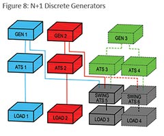
 Similarly, a redundant generator system can be scaled up in capacity without using parallel switchgear. In Figure 8, two generators with two ATSs can support two load groups with 2N redundancy. Again, each primary ATS requires a normal utility power feed, which is not shown for clarity. When total load increases such that a third load group is required to be supported, then a swing ATS can be added to the two original generators. When a fourth load group is added, a third generator, two more primary ATSs and another swing ATS are required.
STSs, Rack ATSs
High-speed, automatic transfer switches include larger static (electronic) transfer switches (STSs) and point-of-use small (typically rack-mounted, contactor type) high-speed transfer switches (rack ATSs). Applying large STSs (static transfer switches) downstream of 2N redundant UPS systems for dual-corded loads provides a convenient maintenance function but can reduce system reliability from 2N to that approaching N+1. Even if redundant A and B STSs are applied, the STS itself includes failure modes that can adversely affect both otherwise isolated UPS systems. The classic combination of tie-breakers and diligent operating procedures can allow for maintenance isolation without using STSs, avoiding cost as well as failure risk. For facilities with a limited number of single-corded loads, small rack ATSs in 2N power distribution configurations solve the problem while limiting the risk of a small ATS failure adversely affecting relatively much larger upstream UPS systems.
Catcher Redundancy
 Catcher configurations, where one backup UPS feeds the internal automatic bypass of one or more primary UPS systems, should be avoided. The backup normally operates at no load for an extended period of time, then needs to suddenly accept high load if a primary UPS fails. Events such as load faults can send the primary UPS to bypass, then immediately send the backup UPS to bypass. Voltage may not hold up for the connected load during successive bypass transfers.
There are many ways to configure redundant UPS and generator systems. Some of the concepts, such as N+1, 2N, 3N/2, etc., applied to power systems can also be applied to cooling (cooling units, backup for chilled water, etc.) and even to control systems such as for building automation and emergency power off systems. Reliability, cost, and operating complexity need to be evaluated and balanced when selecting the best method for a given application.
FIGURE 7: A swing ATS can be used for cooling equipment arranged in groups of three to reduce stranded redundant cooling capacity from 100 percent to 50 percent. For example, if 100 tons of cooling are needed, the A side can provide 50 tons, the B side 50 tons, and the swing ATS another 50 tons.
FIGURE 8: Two generators with two ATSs can support two load groups with 2N redundancy. Each primary ATS requires a normal utility power feed, which is not shown for clarity. When a third load group is required to be supported, a swing ATS can be added to the two original generators. When a fourth load group is added, a third generator, two more primary ATSs and another swing ATS are required. ATSs are shown without the normal utility input to keep the diagram simple.
Michael Fluegeman is principal and manager of data center support systems for PlanNet, an independent professional services firm that provides advisory, design, project management, and construction services supporting critical IT infrastructure. He can be reached at mfluegeman@plannet.com.
Email comments and questions to edward.sullivan@tradepress.com.
Related Topics: