Exploring The Value of 2N Redundancy
Part 3 of a 5-part article detailing the factors involved in deciding the level of redundancy for critical facilities.
In a 2N redundant system (also known as “system plus system”), the redundant components are completely separate (ideally also located in separate rooms). The redundant components do not need to be of the same make and model, or even of the same capacity, although redundant components with different capacities can increase the load management challenge.
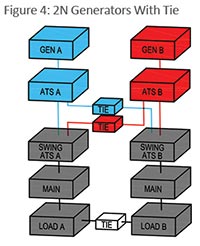
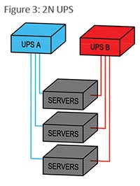 In Figures 3 and 4, blue represents the “A” side and red represents the “B” side. Loads redundantly and automatically supported by both A and B sources, such as dual-corded servers and swing ATS loads, are gray. Dual-corded servers with internal redundant power supplies normally draw half their power from each side but can draw all their power from only one side during a source (or internal power supply) failure.
Using the same example of 100 kW as the load requirement, the simple method would be to apply two 100kW components supporting dual-corded loads or other redundant equipment such as cooling. In the 2N UPS diagram (Figure 3), this provides 100 percent redundancy but also results in 100 percent stranded capacity (200 kW of UPS capacity for only 100 kW of load). In the generator diagram (Figure 4), a mix of N, N+1, and 2N redundant loads (dual-corded servers, etc.) can be connected to reduce stranded capacity. The top two tiebreakers are normally closed to allow the swing ATSs to provide automatic generator redundancy to all swing ATS loads. Non-redundant loads (not shown in diagram) can be connected to primary ATSs, to be supported by only one generator. The bottom tiebreaker is normally open and is only closed manually when both A and B sides are secured to the same source.
 While a straightforward 2N configuration provides better reliability than an N+1 configuration, initial as well as ongoing operating costs will usually be higher because of the 100 percent stranded capacity.
With 2N systems, end-of-life replacement is less challenging than with N+1 systems. One system can be completely offloaded and isolated for replacement while the other system carries the entire load.
Although identical 2N redundant systems are easier to operate and maintain, using identical redundant systems may not be the most reliable approach. The same bad component or incorrect adjustment could adversely affect both redundant systems simultaneously. Or the service technician working on both systems could have a bad day and make the same mistake in multiple areas.
FIGURES 3&4: In Figures 3 and 4, blue represents the “A” side and red represents the “B” side. Loads redundantly and automatically supported by both A and B sources, such as dual-corded servers and swing ATS loads, are gray.
Related Topics: