2(N+1) and 3N/2 Redundancy: High Reliability Options
Part 4 of a 5-part article detailing the factors involved in deciding the level of redundancy for critical facilities.
For the highest reliability, applying an N+1 system as the A side and another complete N+1 system as the B side results in 2(N+1) redundancy. This level of redundancy can tolerate multiple component failures or can maintain N+1 redundancy with an entire system down. There is a high price to pay, however, in initial and operating costs as well as floor space for more than 100 percent stranded capacity. In a worst case, where N = 1, you have 300 percent stranded capacity.
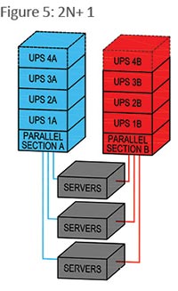 For better reliability, more vendor flexibility, and easier and-of-life replacement, 2N is almost always better than N+1. However, for large systems, the cost for full 2N (100 percent) redundancy can be high. Many UPS vendors offer internally scalable/redundant systems with UPS sections as small as a few kW to as large as several hundred kW. Batteries are typically also redundant. An internally redundant UPS does not cost much more, or take much more floor space, than a non-redundant system. Internally redundant systems are also usually scalable, which allows for better right-sizing of capacity to load and reducing stranded capacity. In Figure 5, two internally redundant N+1 systems are configured effectively as 2(N+1) redundant.
3N/2 redundant
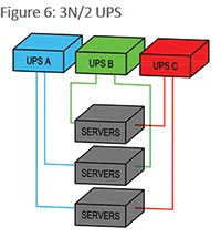
The three-to-make-two or 3N/2 redundant configuration provides nearly 2N reliability with N+1 capital and operating costs, but with added load management challenges. In the 3N/2 UPS example shown in Figure 6, three UPS systems support three load groups. If the total load is 100kW, or in this example each load group is 33kW, each UPS needs to have 50kW capacity to support the total load with one UPS down. Only 50 percent stranded capacity is required. But it is key to balance the loads such that remaining UPSs are not overloaded when any single UPS is down. Equal load groups of three work best for this application. A properly load-managed 3N/2 eliminates the single point failure risk of N+1 parallel systems.
 You could extend 3N/2 further in theory, say to 4N/3 or even further. But if two is company and three’s a crowd, then four or more can be chaos when managing and balancing loads to maintain redundancy, if and when load levels actually get near the design limit. Managing complex redundant configurations is certainly doable with modern DCIM tools, but careful attention to detail is required. And keep in mind that with only one of several units effectively serving as a backup, there are many failure points and only one reserve unit.
A 4N/3 or 5N/4 system may be less reliable than a basic N system, simply because such an elaborate system has so many components that can fail and several load balancing points. A balanced system can tolerate only one failure without overloading the remaining components and an incorrectly load-balanced system may tolerate no failures.
FIGURE 5: Two internally redundant N+1 systems are configured effectively as 2(N+1) redundant.
FIGURE 6: In this 3N/2 UPS example, three UPS systems support three load groups.
Related Topics: